The camera mount came away from the tripod with very little encouragement which made it easier to attached a horizontal cross section which would hold all the elements that form the station. The cross section is a boom from an old HB9CV 4m antenna, with a length of 80cm and 1.6cm x 1.6cm square.
It is attached to the tripod with its antenna bracket using wing nuts so it can be removed by hand if needed. Holes were drilled for attaching the antennas and monitor – but that was the sum total of 'metal work' required.
I decided on having the RX side of the station of the left, with the TX on the right – with the 12v distribution unit in the middle.
The RX antenna is bolted (horizontally polarised) to the boom with it's supplied right angle bracket using wing nuts – it fits very securely to the boom. The RX unit is connected directly to the RX antenna using an N type to RP SMA connector, next is the 7 inch monitor. This has a stand which has been bolted to the boom (some plastic corner blocks have been added to the boom to give extra support) – the angle of the monitor can be adjusted, plus it can be taken off the bracket easily should the need arise. As the monitor does not feature sound, a small set of amplifier speakers are added when needed. The audio out from the RX unit is simply fed into the speakers input socket.
In the middle (to the right of the mast clamp) is the 12v distribution unit. This is attached by gluing a piece of 16mm white plastic coupling (intended for use with 16mm by 16mm MK conduit trunking) to the back of the unit to act like a clip. This allows for the easy removal of the unit and is quite sturdy.
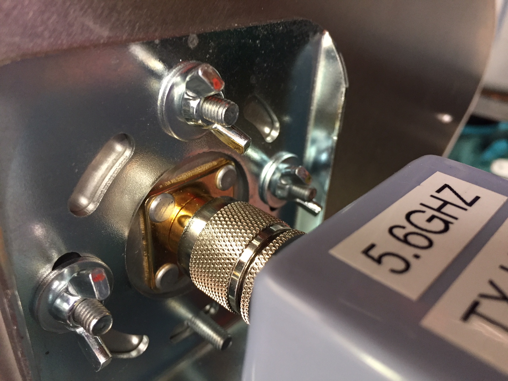
Next is the TX antenna - again attached horizontally with the supplied bracket and wing nuts - with the TX unit connected directly to it, again with an N type to RP SMA connector.
One of the 12v black and white cameras is attached to a piece of 16mm white plastic coupling and can be attached to any part of the boom.
The Media Card Reader (which is used for test card and callsign display) has a 25mm white plastic coupling glued to the back, and this is clipped to one of the tripods legs to keep it securely out the way.
Power leads for all the units are just connected to the relevant socket on the distribution unit, whilst AV leads are run from the RX unit to the monitor for the receive side of the station, and from the camera and media card reader (via the AV switch) to the TX unit for transmission.
It may not be the most lightweight system in the world, but it is for from being unmanageable and it all folds down to fit into the car with out having to dismantle everything (I just remove the 12v distribution unit and camera). And it is light enough to carry short distances if required to help get those few extra meters of height !
The station had a slight rebuild in April 2018 - a new , and more stable, was purchased to allow for easier alignment when out in the field. Also a new (slightly wider) boom was added to increase the stability. Plus a C-DVR (digital AV recorder) was added to enable recording of the transmitted sand received signals so a record could be kept of QSOs. This helps analyse the quality of the signals over the QSO paths and is a nice reminder of what was achieved.